Internal shape specifiers
In the Dimension Table Edit dialog, after selecting the geometric type to use, in the Geometric Shape section you can select the geometric shape to use.
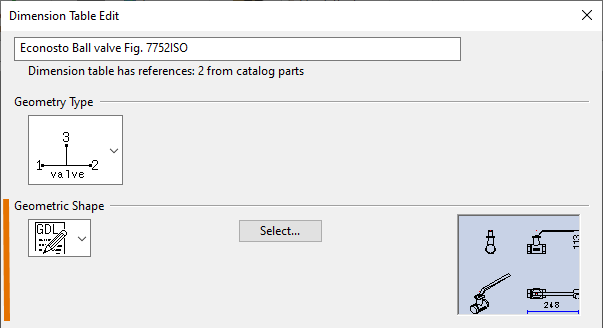
Geometric shape
Each item in the Geometric Shape drop-down menu maps to an internal shape code, as shown in the table below. The table also shows the dimensions that each geometric shape type requires; in the Dimension Table Edit Tool dialog, first you define the dimensions that the geometry type requires (see Geometry types), and then you define the additional dimensions that the geometric shape requires.
|
Symbol |
Symbolic name |
Shape code |
Additional dimensions |
|---|---|---|---|
|
|
0 |
parameters to GDL |
|
|
|
Cylinder |
1 |
diameter |
|
|
Toroid |
2 |
diameter |
|
|
Cone |
3 |
diameter, diameter |
|
|
Flange |
4 |
diameter, thickness |
|
|
Neck flange |
5 |
flange diameter, neck diameter, thickness |
|
|
Beam |
6n |
cross section id number |
|
|
Plate |
7 |
thickness of plate |
|
|
(no shape) |
8 |
|
|
|
Eccentric cone |
9 |
diameter, diameter |
|
|
Oval airduct |
10n |
wall thickness, width, height |


For all geometric shapes, the quantity type of both width and height is always Length.
For geometric shapes other than oval airduct, the quantity type of thickness is always Length.
For beams, the quantity type of cross-section ID is Pieces. The ID values are defined in the Beam cross-sections configuration object.
Beam profile
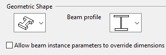
If Geometric Shape is set to the beam shape type, you must also select the beam profile and whether to allow designers to override Dimension Table values with instance parameters.
Each item in the Beam profile drop-down menu maps to an internal profile code, as shown in the table below. The profile code numbers are needed, for example, when defining beam classes, as described in Beam classes.
|
Symbol |
Profile code |
Shape code |
Description |
Required dimensions |
|---|---|---|---|---|
|
|
0 |
60 |
user defined, nonstandard |
|
|
|
1 |
61 |
L with equal sides |
|
|
|
2 |
62 |
L with different sides |
|
|
|
3 |
63 |
L, general |
|
|
|
4 |
64 |
U |
|
|
|
5 |
65 |
T |
|
|
|
6 |
66 |
I |
|
|
|
7 |
67 |
Square cross-section |
|
|
|
8 |
68 |
Rectangular cross-section |
|
|
|
9 |
69 |
n-polygon |
|
|
|
10 |
610 |
Double-web I-profile |
|
|
|
11 |
611 |
Non-equal I-profile |
|


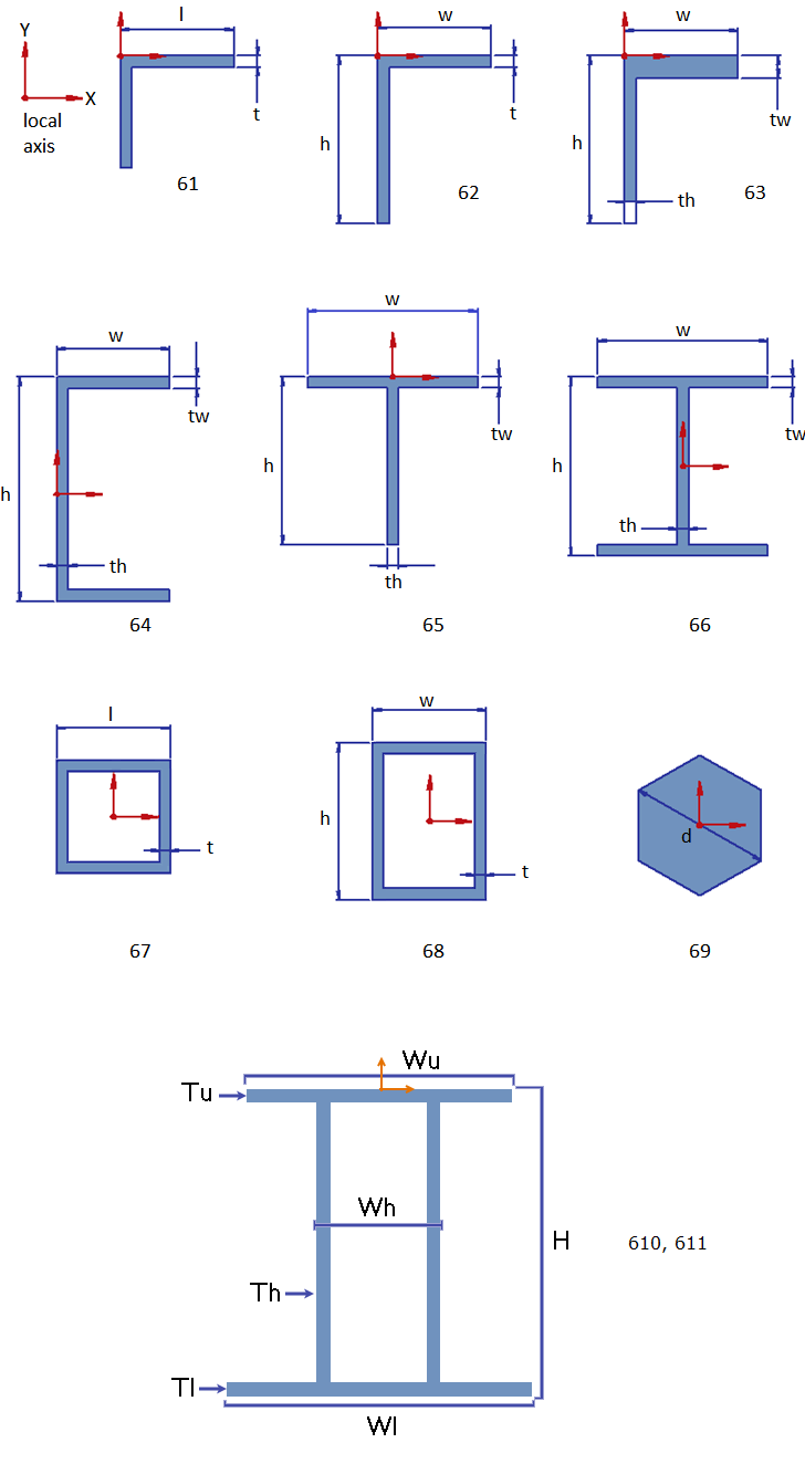
For profiles 67 and 68, the quantity type of t can be Length or Wallt.
For other profiles, the quantity type of t, th and tw must be Length.
The dimensions of the beam profile types are shown below.
Airduct profile
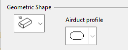
If Geometric Shape is set to the airduct shape type, you must also select the airduct profile.
Each item in the Airduct profile drop-down menu maps to an internal profile code, as shown in the table below.
|
Symbol |
Profile code |
Shape code |
Description |
Required dimensions |
|---|---|---|---|---|
|
|
1 |
101 |
Oval |
Wall thickness, width, height |

Measures in Dimension Table
First wall thickness measure = wall thickness.
First length measure = width.
Second length = height.